TL;DR
- How Night Vision Works: Photons of invisible infrared and low-level ambient light pass through the objective lens and strike a photocathode, converting them into photoelectrons. These electrons are multiplied via a microchannel plate (MCP) and accelerated onto a phosphor screen, converting them back into visible photons to create the intensified green or white image you see.
- FOM, Resolution, and SNR: Figure of Merit (FOM) is a commonly used combined performance metric calculated by multiplying resolution by Signal-to-Noise Ratio (SNR). Resolution (measured in lp/mm) determines the ability to resolve fine image detail, while SNR measures the ratio of useful image signal to noise within the intensifier output. Higher resolution and SNR generally contribute to a cleaner, more detailed image.
- Autogating and Manual Gain: Autogating dynamically modulates photocathode voltage in response to changing light levels, helping control tube operation, reduce saturation and blooming, and maintain image quality when moving between dark environments and bright light. Manual gain allows the operator to actively adjust image brightness to optimize viewing comfort and image appearance for changing ambient conditions.
History and Generations of Night Vision
Night vision technology evolved through distinct technological leaps, traditionally categorized into generations that describe major changes in tube architecture, photocathode technology, and overall performance.
- Gen 0 (1940s–1950s): Gen 0 systems represented the earliest practical generation of electronic night vision. These systems used image-converter tubes with photocathodes sensitive to near-infrared light and generally relied on active infrared illumination to provide usable images. They did not use the microchannel plate found in later Gen 2 and Gen 3 systems, resulting in comparatively limited sensitivity and image quality. Gen 0 technology established the fundamental electronic image-conversion principles that later generations would refine.
- Gen 1 (1960s): Gen 1 systems represented the transition toward practical electronic night vision capable of operating with available ambient light such as starlight and moonlight, although active IR illumination remained common. These systems used glass-window vacuum tubes that offered basic light amplification but suffered from heavy peripheral distortion, image lag, and high sensitivity to blooming when exposed to bright light sources such as streetlights.
- Gen 2 (Late 1960s to 1970s): The introduction of the Microchannel Plate (MCP) was the defining technological advancement of Gen 2 night vision. Placed between the photocathode and phosphor screen, the MCP multiplies electrons through a cascading secondary-emission process, providing substantially greater electron amplification and image brightness. Gen 2 systems generally offered significantly improved resolution, reduced distortion, and better low-light performance compared with Gen 1 systems.
- Gen 2+ (Industry/Marketing Designation): Gen 2+ is not a formally standardized generation in the same way that the traditional Gen 1, Gen 2, and Gen 3 classifications are commonly used. Instead, Gen 2+ is an industry and marketing designation generally used to describe improved Gen 2-based image intensifier tubes that incorporate advancements beyond earlier Gen 2 designs without using the gallium arsenide (GaAs) photocathode characteristic of Gen 3. These improvements may include enhanced photocathode performance, improved signal-to-noise ratio, higher resolution, reduced halo, improved manufacturing consistency, and other refinements to the tube's electrical or optical performance. Gen 2+ tubes generally do not qualify as Gen 3 because they retain Gen 2 photocathode technology rather than using a GaAs photocathode. Performance specifications can overlap between high-performance Gen 2+ and lower-spec Gen 3 tubes, so the generation designation alone does not necessarily indicate the actual performance of a particular tube. Because there is no single universal specification defining Gen 2+, the specific tube's datasheet specifications — particularly resolution, SNR, gain, photocathode sensitivity, and other available metrics — are more meaningful than the Gen 2+ label alone.
- Gen 3 (1980s to Present): Developed primarily in the United States, Gen 3 introduced gallium arsenide (GaAs) photocathodes, providing substantially higher quantum efficiency, particularly in the near-infrared spectrum where night-sky illumination is prominent. Gen 3 tubes incorporated an ion-barrier film to protect the photocathode from ion damage and extend tube life, though modern unfilmed variants remove this barrier for higher light transmission and improved sensitivity and signal-to-noise performance.
- Unfilmed Gen 3: Within modern Generation 3 technology, tube construction branches into filmed and unfilmed variants. Traditional thin-filmed tubes retain a microscopic ion-barrier layer that protects the gallium arsenide photocathode from ion damage during operation, enhancing longevity at the expense of some light transmission. Unfilmed Gen 3 tubes remove this barrier entirely, reducing electron scattering and increasing electron transmission to improve sensitivity, signal-to-noise ratio, and edge-to-edge clarity in ultra-low-light environments.
Deep Dive: How Image Intensification Works
At a microscopic level, an image intensification tube is a sophisticated vacuum chamber designed to convert invisible photons into visible light through a multi-step quantum and electronic process:
- Photocathode Conversion: Photons from low-level ambient light enter the device through the objective lens and strike the photocathode — a thin, specialized semiconductor layer bonded to the input window. When a photon hits the photocathode, it excites an electron, causing it to be released into the vacuum of the tube as a photoelectron via the photoelectric effect.
- Electron Acceleration: Once released, these photoelectrons are accelerated across the vacuum gap toward the microchannel plate by a high electrical voltage (typically several thousand volts) applied between the photocathode and the input of the MCP.
- Multiplication via the Microchannel Plate (MCP): The accelerated electrons enter the MCP, which is a tiny glass disk containing millions of microscopic, parallel hollow channels tilted at a small angle. As an electron enters a channel, it strikes the walls, knocking loose secondary electrons. These secondary electrons bounce down the channel in a cascading avalanche effect, multiplying the single original electron into thousands of electrons while preserving the spatial information of the original image.
- Phosphor Screen Illumination: The amplified electron population exits the MCP and is accelerated across another high-voltage gap toward the phosphor screen. When the high-energy electrons strike the phosphor coating, the screen releases photons, creating a bright, detailed visual representation of the original scene.
- Output Window Construction: Depending on the specific tube design and optical layout, the resulting optical image exits through the output window, which may incorporate a fiber-optic element designed to transfer the image cleanly to the eyepiece assembly.
Detailed Breakdown of Specification Sheet Values
When evaluating night vision performance, specification sheets provide standardized metrics that indicate how well a tube will perform in various environments:
- Signal-to-Noise Ratio (SNR): SNR measures the ratio of useful image signal to noise within the intensifier output. A higher SNR generally produces a cleaner, more usable image, particularly under very low-light conditions, where noise and scintillation become more prominent.
- Resolution (lp/mm): Measured in line pairs per millimeter, resolution is determined using a specialized target chart viewed through the optical assembly. It indicates the tube's ability to resolve fine details. Actual system resolution depends on both the intensifier tube's native capability and the optical performance and alignment of the matched objective and eyepiece assemblies.
- Figure of Merit (FOM): Calculated as Resolution × SNR = FOM. While used in various regulatory and export contexts as a shorthand benchmark of tube capability, FOM is fundamentally a combined performance metric and does not capture every variable of image quality, such as contrast, halo, or EBI.
- Halo: The bright ring or distortion that appears around high-intensity light sources within the field of view. Measured in millimeters, a smaller halo generally indicates less image-area obscuration around bright light sources when transitioning through urban or mixed-light environments.
- Cathode Sensitivity: Measures how effectively the photocathode converts incident light into photoelectrons, quantified in microamperes per lumen (µA/lm). Higher sensitivity means the tube can extract more usable signal from very dim starlight or overcast night skies.
Phosphor Screen Variations: Green, White, and Legacy Compounds
The phosphor screen is the final stage of an image intensifier tube, coating the interior surface of the output window to convert accelerated electrons back into visible photons. Over the decades, tube manufacturers have experimented with various chemical formulations to optimize image contrast, decay time, and human visual response.
- Legacy Phosphor Compounds (P1, P20, and Early Variants): Early generation systems utilized phosphors such as P1 and P20 (often described as mustard or yellow-green), which featured noticeable persistence and decay characteristics that influenced image lag in early night vision systems.
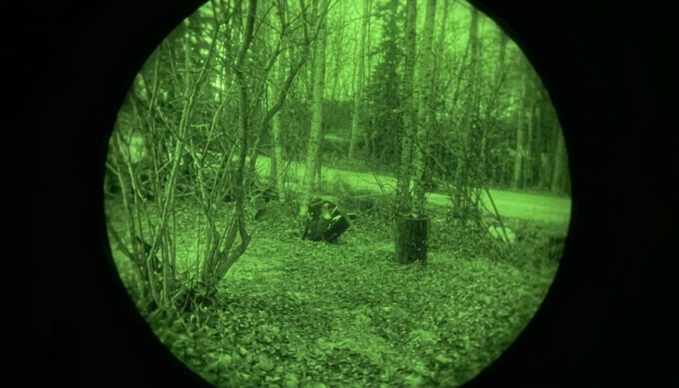
- P43 Green Phosphor: P43 became a widely used standard green phosphor for military and tactical night vision systems. It emits a narrow green wavelength spectrum (~545 nm) that aligns closely with the peak sensitivity of the human eye.
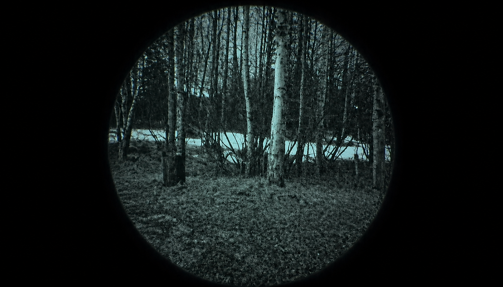
- White Phosphor (P45 and Proprietary Blends): Modern tactical systems frequently utilize white-phosphor screens, including P45 and other proprietary phosphor formulations. Rather than producing a predominantly green image, white phosphor produces a grayscale or near-grayscale image. Many operators prefer white phosphor because the grayscale output can provide subjectively improved contrast and edge-detail perception during extended use.
Environmental Durability and Housing Specifications
Beyond the internal optical intensifier tube, practical night vision performance relies heavily on physical housing integrity and ruggedization to survive harsh field conditions:
- Nitrogen Purging: Many tactical housings are purged with dry inert gas such as nitrogen or argon and sealed to reduce internal moisture and condensation caused by environmental temperature changes.
- Waterproofing Standards: Water resistance is model-specific; manufacturers test and specify exact IP ratings or maximum immersion depths rather than assuming universal compliance across all tactical systems.
- Material Construction and Drop Resistance: Housings may be constructed from reinforced polymers, aluminum alloys, or other lightweight structural materials designed to protect the internal optics and image intensifier from impact and environmental stresses in the field.