TL;DR
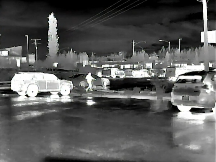
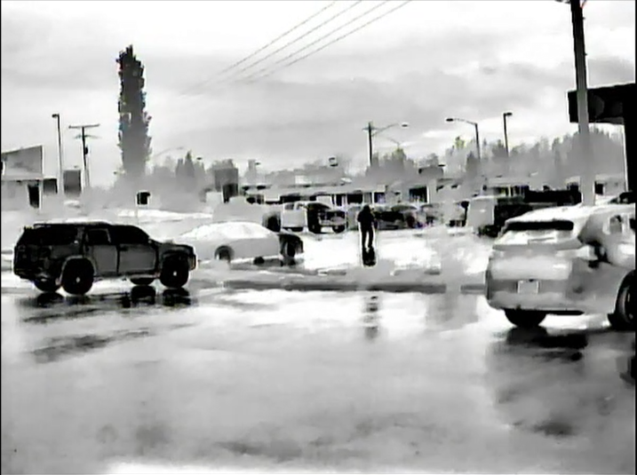
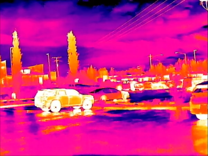
- How Thermal Imaging Works: Thermal sensors detect infrared radiation that objects emit based on their own temperature, rather than relying on reflected visible or near-infrared light. This means thermal can produce a usable image with zero ambient light, though heavy fog, rain, smoke, and dense vegetation can still degrade performance.
- Resolution, Refresh Rate, and NETD: Sensor resolution (from 160×120 up to 1024×768+) determines image detail and identification range. Refresh rate (9Hz vs. 30–60Hz) determines how smooth motion looks during tracking or movement. NETD (measured in mK) determines how small a temperature difference the sensor can actually distinguish — lower NETD means more usable contrast between a target and its background.
- Form Factor Drives the Rest: Handheld, weapon-mounted, and helmet-mounted thermal systems are built around different priorities — a helmet system favors a wide field of view near unity magnification for natural movement, while a weapon-mounted system is built to survive recoil and hold zero, and a handheld unit trades some of both for portability.
History and Evolution of Thermal Imaging
Thermal imaging technology originated primarily in military and industrial applications before expanding into commercial, automotive, and consumer markets. Its development progressed from active infrared systems and mechanically scanned detectors to cooled focal-plane arrays and, eventually, compact uncooled microbolometers.
- Early Military Origins (1930s–1950s): Early military night-vision systems developed during World War II and the early Cold War included active near-infrared devices such as the American M3 Sniperscope. These systems used an infrared illuminator to project invisible IR light onto a scene and an image-converter tube to detect the reflected illumination. Although important to the history of night vision, these systems were not thermal imagers because they detected reflected near-infrared light rather than thermal radiation emitted by objects. Passive thermal imaging began emerging as detector and infrared-optics technology advanced during the 1950s and 1960s.
- Early Thermal Scanners (1950s–1970s): Early thermal imaging systems commonly used small numbers of infrared detector elements, including materials such as mercury cadmium telluride (HgCdTe), to detect long-wave infrared radiation. Many high-performance detectors required cryogenic cooling to reduce thermal noise and achieve useful sensitivity. Mechanical scanning systems used mirrors, prisms, or other moving optical components to sweep the scene across the detector. These systems were generally bulky, power-hungry, and expensive, restricting their use primarily to military vehicles, aircraft, ships, and fixed surveillance installations.
- Staring Arrays and Second-Generation Systems (1980s–1990s): The transition from mechanically scanned systems to solid-state staring focal-plane arrays (FPAs) represented a major advancement in thermal imaging. Instead of mechanically sweeping a single detector across the scene, an FPA uses an array of detector elements that simultaneously observe different portions of the image. Cooled semiconductor FPAs continued to provide exceptional sensitivity for demanding military applications, while uncooled detector technologies — including pyroelectric devices and emerging microbolometers — began enabling smaller and less complex systems.
- The Microbolometer Revolution (Late 1990s–2000s): The commercial maturation of uncooled microbolometer technology transformed thermal imaging. Microbolometers detect infrared radiation by measuring temperature-dependent changes in the electrical properties of microscopic detector elements. Because they operate without cryogenic cooling, they can be manufactured into compact, relatively low-power sensor modules. This development enabled widespread adoption of thermal imaging in handheld cameras, weapon sights, surveillance systems, industrial diagnostic equipment, and other portable applications.
- Miniaturization and Commercial Expansion (2010s–Present): Continued advances in semiconductor manufacturing, detector fabrication, signal processing, and optical design have steadily reduced pixel pitch while increasing sensor resolution and reducing overall system size and power consumption. Common modern thermal sensor formats range from compact 160×120 and 256×192 arrays through 320×240, 384×288, 640×512, and higher-resolution formats such as 1024×768. Modern thermal cores can be compact and rugged enough for integration into handheld devices, weapon sights, helmet-mounted systems, vehicles, industrial equipment, and consumer electronics.
Sensor Resolution and Pixel Pitch
The core of a thermal imaging device is its focal-plane array (FPA), which contains the individual detector elements used to capture infrared radiation. The number of pixels determines the native image dimensions, while pixel pitch describes the physical spacing between adjacent detector elements. Common commercial and tactical sensor resolutions include:
- 160×120 and 256×192: Common in compact, entry-level, and cost-sensitive thermal devices. These lower-resolution arrays can provide useful detection and observation capabilities but generally provide less fine detail and shorter identification ranges than higher-resolution sensors when other factors are equal.
- 320×240 / 384×288: Widely used mid-range formats that provide a balance between image detail, processing requirements, power consumption, and system cost.
- 640×512: A widely used high-resolution format in professional and tactical thermal systems, providing substantially more image detail than lower-resolution arrays and allowing greater flexibility in optical design and digital magnification.
- 1024×768 and Higher: High-resolution thermal formats used in higher-end systems where increased spatial detail, wider fields of view, or longer-range identification capability justify the additional cost and system requirements. These higher-resolution sensors generally come at the expense of increased per-unit cost, greater processing requirements, and potentially increased system weight and power consumption. The additional pixel count can also require more powerful image processing and higher-bandwidth electronics to maintain comparable refresh rates and image quality.
Sensor performance is also influenced by pixel pitch, which is the distance between the centers of adjacent detector elements. Common modern microbolometer pixel pitches include 12 µm and 17 µm, with smaller pitches also available. A smaller pixel pitch allows more detector elements to fit within a given physical sensor area or allows a smaller sensor for a given pixel count. Pixel pitch also interacts with lens focal length, detector format, and optical design to determine field of view, angular resolution, and system size.
Lens Focal Length, Field of View (FOV), and Magnification
The objective lens determines how much of the scene is projected onto the thermal sensor. Its focal length, combined with the physical dimensions of the sensor, determines the system's field of view and base optical magnification.
- Wide-Angle Lenses (Shorter Focal Lengths): Lenses in the approximately 9mm to 19mm range are commonly used where a wide field of view is desirable, such as helmet-mounted observation, close-range scanning, navigation, and situational awareness. The exact field of view depends on both the lens focal length and the physical dimensions of the sensor.
- Narrow-Angle Lenses (Longer Focal Lengths): Lenses in the approximately 35mm to 75mm or greater range provide a narrower field of view and greater optical magnification. These configurations are generally better suited to longer-range observation and target identification, although the resulting narrow field of view can make close-range scanning more difficult.
For helmet-mounted thermal usage, optical magnification and field of view are particularly important because the thermal image is presented on a display rather than directly through an image-intensifier output. A wide field of view and an appropriate display-to-optical configuration help provide a natural visual relationship between the displayed thermal scene and the user's surroundings. Systems intended to provide approximately 1× or unity magnification are generally easier to integrate with natural head movement and navigation, while magnified systems can make walking, driving, and close-range spatial awareness more difficult.
True unity magnification is determined by the complete optical system rather than by the sensor alone. The sensor format, pixel pitch, objective focal length, display size, display optics, and eyepiece design all contribute to the final angular magnification and field of view perceived by the operator.
Refresh Rates and Motion Handling
Thermal refresh rate describes how frequently the system updates the displayed image and is measured in Hertz (Hz). A higher refresh rate generally provides smoother perceived motion, although actual motion performance is also influenced by sensor integration time, image processing, display latency, and other system characteristics.
- 9 Hz: Low-refresh-rate thermal systems update the image relatively slowly, which can make rapid movement appear noticeably less fluid. Low-refresh-rate configurations have historically been common in some commercial thermal products because of regulatory, export, cost, or product-design considerations, although the availability of specific refresh rates varies by manufacturer and market.
- 30 Hz to 60 Hz: These refresh rates are common in modern tactical and high-performance thermal systems. Higher refresh rates provide smoother motion during head movement, vehicle operation, and tracking of moving subjects, while also reducing the apparent stutter associated with lower-refresh-rate systems.
Thermal Sensitivity (NETD)
Noise Equivalent Temperature Difference (NETD) is a measure of a thermal sensor's ability to distinguish small differences in apparent temperature from the sensor's own noise. It is typically expressed in millikelvin (mK). Lower NETD values generally indicate that the sensor can detect smaller temperature differences under the specified test conditions.
Modern thermal sensors may be specified with NETD values such as sub-40 mK or sub-25 mK. Lower NETD can be particularly advantageous when a target and its background have only a small thermal contrast. However, NETD is not a complete measure of thermal-image quality or real-world performance. Lens transmission, sensor resolution, pixel pitch, atmospheric conditions, image processing, calibration, optical quality, and the thermal contrast of the scene all affect how well a system performs in practical conditions.